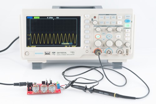
Oscilloscope

An oscilloscope is an electronic test instrument used to observe and analyze the varying signal voltages in electrical and electronic circuits. It displays waveforms on a screen (traditionally CRT, now mostly digital LCD/LED), allowing users to visualize how signals change over time. Engineers, technicians, and researchers use oscilloscopes to measure signal frequency, amplitude, rise time, distortion, noise, and other characteristics. Oscilloscopes are essential in electronics design, troubleshooting, research, and quality control, as they provide real-time graphical representation of electrical signals.
- Display of Waveforms – Shows signal voltages as a function of time in graphical form.
- Dual / Multiple Channels – Allows simultaneous measurement of two or more signals for comparison.
- Time Base Control – Adjusts the horizontal scale to expand or compress the signal for detailed analysis.
- Voltage Scale (Vertical Control) – Adjusts the vertical sensitivity to measure small or large voltages.
- Triggering System – Stabilizes waveforms by locking the display to a repeating signal.
- Measurement Functions – Provides automatic measurements such as frequency, period, RMS, peak-to-peak voltage, duty cycle, etc.
- Storage Function (in Digital Oscilloscopes) – Stores waveforms for later analysis and comparison.
- Bandwidth – Determines the frequency range of signals that can be accurately measured.
- Sampling Rate – In digital oscilloscopes, defines how many data points per second are captured for waveform accuracy.
- Probes – Connects the oscilloscope to the circuit, available as passive or active types.
- Math Functions – Addition, subtraction, FFT (Fast Fourier Transform) for frequency domain analysis.
- Connectivity – Modern oscilloscopes include USB, LAN, or Wi-Fi for data transfer and remote operation.